Introduction
To explain what this project is, I should probably start with what it is intended to be used for: the "C3 board".
The C3 board, or Credit-Card Computer (yes that is literally what the acronym stands for), is a single-board computer developed in collaboration between the University of Alberta (my university), and a company based out of Edmonton known as Eleven Engineering Inc. My understanding is that Eleven Engineering is responsible for the design of XinC2 CPU, a RISC-V based processor that the company uses for their digital audio products. It's a 16-bit RISC-V multithreaded processor featuring 8 hardware threads. It's actually a much more exotic piece of hardware than what the Eleven Engineering website would suggest, but that's a discussion for later in the article. The C3 board that utilizes the XinC2 CPU was made by previous electrical engineering capstone students from the U of A. Some of the details of this board (and the XinC2 CPU, for that matter) are confidential so I can't share everything about them. However, I'll share some of the most important details. This board has some interesting system limitations that make it a little more challenging to work with. Notably, RAM is extremely limited with only about 32kB of SRAM to work with. The system also lacks a stack, so dynamic memory allocation is out of the question. Additionally, the board also doesn't have an OS. All software you write for the board has to run on bare metal, which makes it feel like programming a microcontroller as opposed to a full computer. These limitations mean you have to get really creative with your software implementations.
As a result of the C3 being a little more exotic, many of the existing programs that exist out there cannot run on this board, or cannot be easily ported to the board. The entire software ecosystem for the C3 board must be created from scratch from the ground up. And as you can probably imagine, completely inventing an entire ecosystem for a completely novel computing platform from the ground up is a MONUMENTAL task. This is where my capstone comes in.
At my university, the way they handle computer engineering capstone projects is that they offer a bunch of pre-selected projects with requirements right out of the gate. You get to form a group, pick a project (first come first serve) and work on that for 4 months. These projects vary wildly, but always involve both a software and hardware component. Of these projects, some of them are for the C3 board and its software ecosystem. My capstone group was formed specifically to take on one of these projects. We chose computer engineering students with a background in more hardware-related tasks to try and improve our odds of success. The catch with these C3 capstone projects is that you have to take two of them, not just one. That's how we ended up with both the SD card file system and the screen file editor.
So, what actually do these two projects constitute?
Starting with the SD card file system (SDFS), it consists of whatever low-level code is needed to get the board to be compatible with microSD cards. At the time we started the project, it actually had no support for external storage, and thus no permanent files could work with it. This is pretty obviously a serious limitation of the C3 platform, and so the SD card File System sought to fix this.
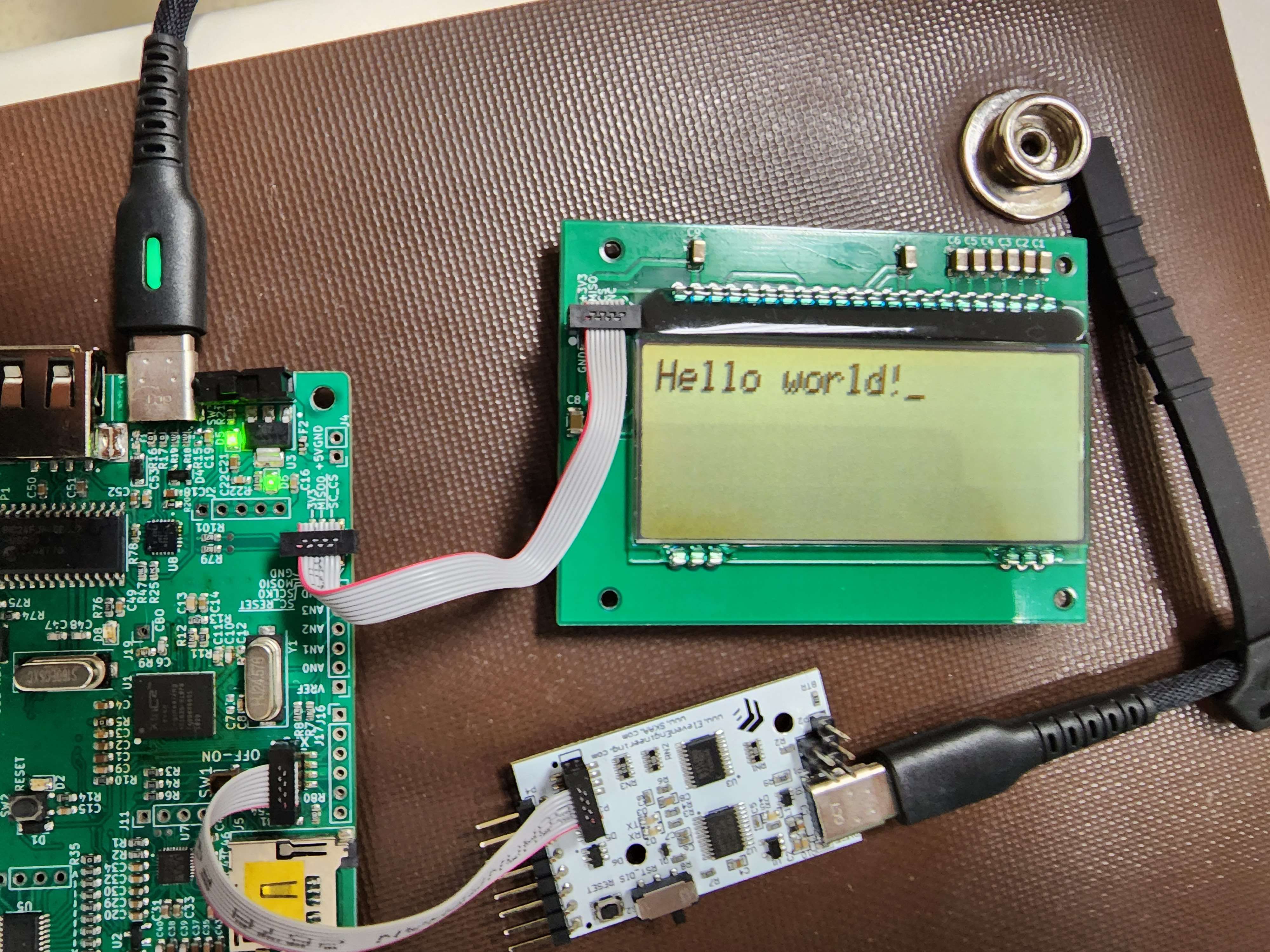
Another limitation of the C3 board, if you ignore the lack of an existing filesystem, is the inability to edit files natively on the C3 board. Currently the only way is to remove the storage medium, edit the file(s) on another computer, and return it to the C3 board. The Screen File Editor (SFE) project aims to fix that by bringing a native text editor to the C3 board ecosystem. It gets its name from the fact that the original specification intended for the Screen File Editor had it running on the C3 board's LCD board.
Design - SD File System
Important preface: I was more involved in the development of the SFE, not the SDFS. The following information comes from our final report. I don't have as intricate knowledge of how things shaped up through development for the SDFS.
Requirements
The SD File System project was split into two components, which were further broken down into four subcomponents:
-
SD Card Driver - Responsible for the low-level communication between the application and the SD card over the C3 board's SPI line.
- Copy
- Load
- Save
- Delete
-
File System API - A high-level API that lets applications easily plug into the file system and interact with files.
- Copy
- Load
- Save
- Delete
The choice to take the SD File System and split it into low-level and high-level code was not a hard requirement from our client. In fact, a lot of the requirements for the SDFS were very loosely defined initially. A lot of the requirements needed to be discussed further after the initial proposal response to learn more about SD constraints (ie. what file system to implement). There were some conflicts between what the client was requesting and what was practical, such as FAT16 vs. FAT32. Ultimately, we settled on a FAT32 implementation because it could be used directly with most modern computers. This would make the most sense when it came to both debugging the SDFS as well as our demonstration that comes as part of the final presentation of our capstone.
Additionally, the SDFS needed to be hierarchically-structured (like a typical OS), and communications needed to occur over SPI (due to hardware limitations with the C3 board). Hierarchical structure was a hard requirement insisted on by the client (AFAIK), but the SPI requirement wasn't written in paper anywhere. Instead, this requirement is more of a hardware constraint that comes with the C3 board and how you're supposed to interface with the SD slot.
Implementation
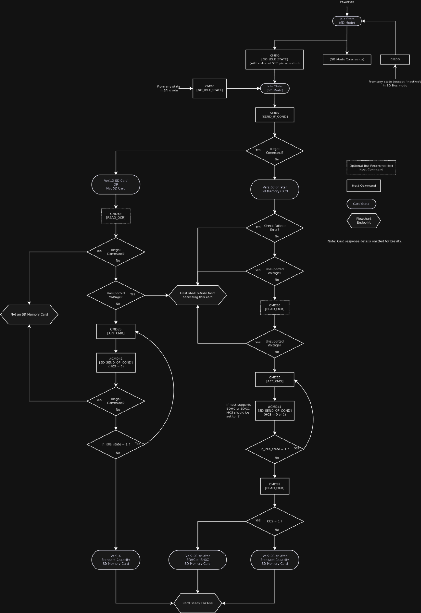
A diagram explaining the boot sequence of the SD File System.
The development of the SD Card Driver, which was done first, involved creating commands to run over SPI. The first set of commands were the initialization sequence, which was a little complicated to implement. The read and write commands, written immediately afterwards, were relatively straightforward in comparison. After that, everything else was implemented through trial and error.
One of the areas that took some work was the boot sector. When I say "trial and error" above, this is specifically what I am referring to (among other things of course). Some of the process could be learned from how typical SD cards work of course, but other features were a little more unique to the C3 board.
Design - Screen File Editor
Requirements
The main requirements for the Screen File Editor were determined by lots of conversations with our client (Eleven Engineering). We came up with the following:
- Must be able to view and edit the contents of a file
- Can save and load files through the SDFS
- Supports both the native C3 LCD screen as well as externally-connected terminals via USB-C port
Architecture
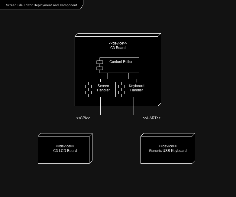
An architectural diagram that came from our capstone's preliminary design document.
To design the text editor, we needed an architecture that broke up the major tasks of the program into high-level components. With a fair bit of discussion, we came up with the following:
-
Screen Handler
- This is the section of the software responsible for rendering file contents, cursors and so on.
It doesn't take ownership of the file contents, but rather maintains a pointer to the text and draws upon it when the main
render()function is called. - Keyboard Handler - This is the section of the code that handles all forms of user input. In a nutshell, it is a glorified multiplexer between the terminal you run on your computer and the C3 LCD/connected USB keyboard. Its main function is to receive user input depending on the mode, and relay that input to the core of the program.
- Content Editor - The "core" of the software that interprets user commands and transforms the file data respectively. This receives commands from the Keyboard Handler and interprets them. It also controls the "mode" of the program (discussed more later, but think of them like Vim modes), move the cursor, and so on. Once these commands are handled, the in-memory file representation is altered, and the Screen Handler is triggered to update the screen.
Input Handling
Our program took a lot of inspiration from Vim for a number of reasons. It is one of the most well-known CLI-based text editors out there. It is very popular and has a loyal fanbase. I also personally liked the clean, minimal interface of Vim compared to other common options such as GNU Nano. As such, we borrowed the idea of having multiple different modes of operation from Vim. This came about for a couple of reasons, but most notably the existing driver code for receiving user input from your connected PC's keyboard was very primitive and could not capture arrow keystrokes. This meant we needed to use other keystrokes that DID work to navigate the file with a cursor, and the only ones that worked were ones that needed to have some kind of representation within files as data (characters, numbers, symbols, newlines, etc). This made having multiple modes that interpret the raw keystrokes different was important. Thankfully, the drivers could differentiate "Ctrl+Letter" from individual letter keystrokes, so we relied on Ctrl to handle important commands, which makes our program more similar to GNU Nano in that way.
We split up the operation of the program into two modes: Command Mode and Edit Mode. Command mode is similar to the default mode in Vim, where keystrokes are interpreted as controls for the program rather than manipulations/additions to the data. For example, the A and D keys, when used in Command mode, move the cursor left and right respectively. The second mode, Edit Mode, should be obvious: keystrokes are interpreted as characters to be typed into a file. To switch between these modes, press Ctrl+E.
To switch between Command mode and Edit mode, press Ctrl+E. There were a couple of other Ctrl commands, such as Ctrl+S for saving, but due to reasons explained below, these were not of much use.
One frustrating quirk with the keyboard input drivers is that they lacked support for a raw input mode. Every time we wanted to enter a keystroke, it had to be followed with an Enter keystroke to send it. This is because the drivers only terminate the buffer that stores the keystrokes once a newline character is detected. We did take a look at the driver code and see if we could implement raw input mode ourselves, but with the timeline we had, it was not feasible. This means that while we could take in user input, it was clunky because every other input had to be the Enter key.
Rendering the Application
During the prototyping stage, we quickly realized that there were quite a few limitations we needed to work around to make our application not look hideous. A lot of the "nice-to-haves" with terminals were not included, such as built-in functions to clear the terminal. This means that to clear the terminal to re-render the screen, we had to do so manually with a function that printed a bunch of newline characters. This is really not ideal for a lot of reasons: inefficient, poor performance, users who accidentally scroll up in the terminal will see previous frames from the GUI, etc. But unfortunately, this is the best we had to work with. This actually is more interesting than just "gross and a little inefficient" however. As mentioned above, the XinC2 CPU on the C3 board runs at about 100 MHz, meaning that by modern computing standards it is not very fast. It also turns out that any statements that need to go between the C3 board and the external computer through the XPD have significant overhead. When you print a bunch of characters (ie. newline chars) in sequence, the board actually takes time to print them all! It's still pretty quick but it's not instant, and you can notice it. This is really undesirable for our program for obvious reasons. It causes a weird-looking flicker effect every time you time which would be super annoying if this was a practical text editor. I will admit though that a part of me kind of likes the "retro computing" vibe the flicker gives.
Another interesting C3 quirk: we had to build a better version of the built-in "print string" function in order for our program to work.
This is likely another contributor to the overhead we encountered when printing things, but it was necessary.
The C3 standard library included two functions for printing strings: a putchar() method for individual characters, and a puts() method for entire strings (char arrays).
Something that was brought to our attention when discussing the C3 board with other groups is that puts() had a bug in it that made it occasionally print garbage text to the terminal.
It was seemingly random, but we speculate it had something to do with some internal buffer somewhere not being cleared.
We got the interface to render the way we liked using ANSI escape sequences, which thankfully worked on the board. We used the "invert text" sequence to create a single inverted character in the printed output, which we used as a cursor. We did also experiment with a "clear terminal" character but had little luck getting it to work correctly. Something we noticed is that the ANSI escape sequence support was spotty across the different PC platforms we tested on, so we also created a "no-ANSI mode" that was a little uglier, but omitted sequences and still worked.
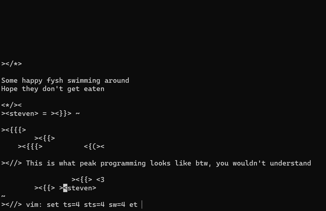
An example text file being edited inside of the Screen File Editor. This file comes from another capstone group working on an esoteric programming language called "Fysh", who graciously gave us permission to use their example programs in our text editor demo. The bottom line of text (the Vim command) can be ignored, it was erroneously copied from one of the example files for some reason :)
The C3 Board is Kinda Weird
I knew that I had to write a bit about this after my experience working with the C3 board. I'm covering it at this point in the page because this section greatly contextualizes some of the results, and more importantly why certain things turned out the way that they did. As you can probably guess by the heading title, the C3 board is an interesting board to develop applications for.
Lack of Support
When we first embarked on this project, we were told that we would be receiving ample support from our client company in order to gain understanding of the C3 board and the XinC2 CPU. This was necessary because our capstone took place over only 4 months, meaning that we had very limited time to build our prototype. We needed as much access to useful resources as possible in order to make a functional prototype in time. Unfortunately, this is not how things played out.
The general consensus from my capstone group is that our client was not very supportive of the projects. They clearly put a little effort in, as they had put together a Discord server dedicated to the C3 board in order to answer questions about the hardware. We were even told by our capstone professor that they were dedicating engineers from their company specifically to answer our questions. However from my personal experience, while the engineers we worked with meant well, they were not helpful at all when it came to answering our questions. They did make (what I perceived to be) an honest attempt to answer them, but I never felt that the answers were of sufficient quality. They never really answered what I was asking directly, and often rarely gave us anything useful. In fact, the only good advice about the hardware we ever got was from other capstone groups working with the C3 board. I did notice that the handful of questions that were specifically about the CPU were answered better than others. And if I remember correctly, Eleven Engineering is only directly responsible for the design of the CPU, not the entire board. This leads me to believe that while Eleven Engineering has a good understanding of the XinC2 CPU, they have very little understanding of the C3 board built around it.
Lack of Functional Drivers
To make matters worse, some of the driver code in the C3 board standard library is just non-functional, at least as of when we received it.
When we first started the project, we got access to a secure drive that contained all of the tools we needed to develop for the C3 board.
This included a C++ compiler, a terminal we could use to interface with the board, a special piece of hardware known as the XinC2 Programming Device (XPD) and a few other pieces of software.
This XPD was of interest in particular because it represented a direct gateway between the realm of computing we understood, and everything that the C3 board is.
One minor frustration we encountered is that while the C3 board's design is somewhat open-source and we were given unrestricted access to what few documents they had on it,
for some reason the XPD was proprietary and we were not allowed to know anything about it beyond how to use it.
This was a little frustrating, but the tools we were given were robust enough that we didn't give this much thought aside from the few times where it could have helped.
However, I would also like to note that no debugger was included with the software, and the C3 board does not support debugging.
This makes working with the C3 board much harder because the best you can do for debugging is print statements, which is not great.
In addition to that, one of the quirks with the C3 board (discussed more in a moment) is the lack of SPI lanes.
The C3 board features only 2 SPI lines, and the built-in print() function takes up one of them.
This means that if you are using a C3 board with other hardware connected to it through SPI, you also cannot simultaneously use print statements to debug.
On the C3 platform, this means it is literally impossible to debug peripherals attached to the board, as they also use SPI to interface with the CPU.
Debugging aside, the other tools worked well thankfully, but that's about where the functional software ends.
We were also given a decently large library of example programs to help us learn about how to write programs for the board. However, none of these example programs actually worked out of the box. They would compile without issue, but when you ran them on the board, the terminal would not show any signs of the program executing successfully. This took us WEEKS to debug, partly due to the poor support outlined above, until we discovered that the issue was simple: the clock speed was configured incorrectly out of the box and needed to be fixed in this one specific header file. This was pretty frustrating at the time but we put it behind us.
The truly egregious failure in the driver code was when it came time for us to start working with the SPI and UART drivers. There were at least 2 example programs that demonstrated each, but none of them worked out of the box either. This went on to become a problem that lasted about 1.5 months, which seriously affected the timeline for building our prototype. It turns out that at some point, the hardware was changed or reconfigured in some way, changing all of the pins and what they did, but the driver code was never updated. It took a collaboration between all the C3-related capstone groups to figure out how to reverse-engineer and patch the existing drivers just so they could work. In a way it was a kind of cool project, as it spanned the entire stack of hardware. We literally had to open up the C++ code, look through each line of code, compare the pins to the ones listed in the XinC2 datasheet, and look for mismatches until we finally figured it out. In the end we got the SPI driver working and distributed to everyone, and only got the UART driver working in the last 2-3 weeks of the capstone, so it was of no use at that point in the project.
To me, it was one thing to mess up something like the clock initialization, but to just forget to update all of your driver code after a major hardware revision? Needless to say, the state things were in, the C3 board probably should not have been given out as a capstone project to work on. It was in a very sorry state when we began.
Threading/Timing Issues
Perhaps the worst issue of all we encountered during development was that of the elusive timing issue. This one is more speculative in nature because we have the least amount of information on it. Several times during development, we ran into instances that look like the following:
                    void A() {
                        ...
                    };
                    void B() {
                        ...
                    };
                    int main() {
                        A();
                        B();
                    }
In any other modern computing system, what would happen is that the code would execute sequentially.
First, the call to A() would execute.
Once that call is done, then B() executes.
There is no overlap between them; it is just one after another.
However, this isn't how the XinC2 CPU works from our experience.
We're not entirely sure of the cause, but we have noticed during development that if A() is a function that takes a while to compute, while
B() is a function that is very quick to compute, the execution schedule will:
- Begin the execution of
A() - Sometime into the execution of
A(),B()will begin execution B()will finish executing as it is much shorter- Finally
A()will finish execution
Also, It Likes to Explode Sometimes
As bad as everything I've mentioned above is, there's one last category of faults with the C3 I think deserves some attention. The C3 board has a tendency to short circuit really easily. In our time working on the C3 capstone, we were extremely careful when it came to handling the board. We would always use anti-static wriststraps, we stored it properly, we were very gentle with the hardware. Despite this, we managed to kill 2 C3 boards in our time developing the projects. Thankfully this was not held against us because the C3 board is extremely cheap to make (we were told each board costs about $5 CAD each) and there were some spares. But how did this happen if we were so careful?
Well, as it turns out, this is partially a PCB issue and partially a hardware issue. There are two major flaws with the design we identified while working with the board. The first one is a PCB design flaw, and it's the layout of the power and ground pins. We noticed that in more than one scenario, the C3 board had male header pins for power and ground that were right next to each other. Theoretically, all it would take is momentary contact between these two pins during operation to fry the board, and when they were only a millimeter apart, many things could accidentally cause this. We speculate this to be the reason for our first dead C3 board.
Now, one fun thing about the C3 board is that if this does happen, it's not completely game over yet. The board has a fuse it uses to protect the critical components, and when the board is shorted, all that happens is that this fuse is blown. You can theoretically desolder the fuse, replace it, and the board will run smoothly again. However's there's another catch with the PCB layout issues: this fuse was placed in the dumbest location imaginable. For whatever reason, the people who designed this board though it would be a brilliant idea to place the fuse basically between the two USB ports on the board. The gap between these ports is extremely narrow and somehow, they managed to fit a fuse in there. But not only a fuse, but debatably the most important fuse on the entire board. So technically, the board can be repaired in the event of a short circuit. However logistically, replacing the fuse is a nightmare. We did attempt this once with one of our dead boards and it took us around 5 hours and 4 different people to try it. In short, it is not practical to repair the board, even if technically possible, so if your board short circuits, just get a new one.
The second hardware issue we identified (and thankfully this did not happen to us) was an issue with the ribbon cables. The board uses these 2x4 headers to connect itself to the LCD board, the XPD, and other external peripherals. However, when we were setting up the board, no instruction was given to us on which way we needed to connect the pins. As we have learned from another group, it turns out if you connect these cables the wrong way, the board short circuits itself and dies. Furthermore, the proper way you're supposed to connect the board looks like the incorrect way due to how the cable bends, so if you go off of intuition alone, you will probably get it wrong. This is a pretty big oversight in the design of the board in my opinion, particularly with how janky the intended ribbon cable connection is.
We're not the only group who burned out a board either. I think every single C3 capstone group destroyed at least one during their time with the capstone. The C3 board is really sensitive and extremely easy to damage compared to other single board computers I've worked with in the past.
Overall, working with the C3 board in general is nothing short of a nightmare. No stack, no debugging, barely any functional drivers, lots of ephemeral timing issues and a poorly-design PCB. I have given the C3 board the tongue-in-cheek title of "Raspberry Pi: Extreme Edition" for a reason. This is not a platform for the faint of heart. It is next to impossible to be productive with this platform when you consider all of the very serious hurdles and limitations you will encounter. I like to think of this board as the hardware equivalent of Malbolge.
I suspect that some of these problems came from the fact that the XinC2, as hinted at in the intro, was designed for digital audio products. It is technically a Turing-complete processor and can perform a wide range of computations like any other RISC-V CPU could. However, there are some features baked into the CPU specifically for digital audio streaming that, while making it suitable for that application, may actively harm more general-purpose computing. At the end of the day, working with such a platform is just an uphill battle when the XinC2 wasn't built for this kind of work. And to make matters worse, when you leave the PCB design in the hands of capstone students (not trying to throw shade at electrical engineering capstone students here, but let's call a spade a spade), you're not getting the best quality of PCB design for a platform that, to be blunt, kind of depends on it.
For all practical intents and purposes, do not use this board ever.
Results - SD File System
In the end, the SDFS was moderately successful. The driver was completed, and the four functions defined above were implemented successfully. The API was not finished in time however, and only the deletion functionality was completed. As you might imagine, the biggest source of our problems were C3-platform-related issues. Incomplete drivers, strange buggy behavior and bad documentation were some of the biggest hurdles I can recall.
-
SD Driver
- Copy
- Load
- Save
- Delete
-
SD API
CopyLoadSave- Delete
Results - Screen File Editor
The SFE was also moderately successful. Due to driver and hardware limitations, some of the project requirements requested by the client were not feasible in the time we had been given. In particular, requirements related to interfacing the C3 board with other components, such as the LCD screen and external USB keyboard, could not be fully implemented. Between the fact we had to patch the drivers ourselves to make them functional and the fact the board has extremely limited SPI lines, it was not feasible to implement the requirements related to interfacing. I was a little disappointed we could not implement this because to me, this would have been the most hands-on, and perhaps the most fun, part of the project if we could make it work. However, as we learned more and more about the C3 platform as we began prototyping with it, the likelihood of us being able to make interfacing work grew slimmer and slimmer. Some of us theorize that some of the SPI-related limitations could be overcome with a more developer SPI driver, as theoretically you can do some bit-banging in order to artificially create more SPI lines in firmware. This actually sounds like a really fun project, but unfortunately given the tight time restrictions of the capstone (4 months), we did not have time to properly explore this avenue.
That being said, our final prototype worked somewhat. It was clunky and impractical, but it did have the ability to show users file contents (sort of) and allow them to make changes to them. Specifically, our text editor had all the logic to print and display file contents stored in the program's memory. As discussed above, we used an in-memory implementation of the file to render and manipulate within the program for ease of use. We likely would have used a more sophisticated implementation that would have prioritized speed if we were not severely limited by the system's RAM and the lack of dynamic memory allocation. However, we opted for the simplest (and not necessarily fastest) implementation due to these restrictions.
Something to note is that due to the tight timeline, while we did get a functioning text editor, it lacks any connection to the SD file system. Our original timeline, assuming no prototyping issues, was to develop the SDFS and SFE independently and spend a week or so integrating them so you could use them together as a full text-editing suite. In practice, due to the various issues mentioned above and the incomplete SD file system API, we did not achieve integration. The text editor behaves more like a "dummy editor" in this regard. The file that we demoed at the capstone expo is pre-loaded in memory, specified in the program's source code. We can render this file and make changes to it, but any "changes" don't get saved to disk, just in memory. In a way it feels a little fake, but I am reassured by the fact that integration with the file system API, which would take at most an hour, would completely fix this issue. It was just purely a necessity for the sake of the capstone expo and our deadline.
Conclusion
Despite the large number of challenges and setbacks, I would still consider the capstone a success (at least somewhat). At the end of the day, we were able to build working prototypes of our projects, even if not 100% complete. I do believe that had the drivers worked out of the box from day 1, we would have easily created 100% complete prototypes. The biggest barrier to our success was definitely the C3 platform itself.
A lot of this probably won't matter in the future because from what I've heard, C3-related capstones are going to be discontinued in the future. I found out that my graduating class was part of a "lab rat" year that these capstones were being tested for. Given that my group, as well as the other groups, had quite negative feedback overall for our client and for the C3 board, we received confirmation from our capstone professor that they're being canned going forward.
There's a part of me that's happy that the C3 board is getting canned. It is an abomination of a computing platform, with inner demons the likes of which I have never seen before in my life. Some of the design decisions and problems this board suffers from are nothing short of baffling: from questionable PCB design, to completely unbaked driver code, zero debugging capabilities, strange hardware limitations and some very questionable timing issues.
However I will admit that the board, in spite of its ungodly flaws, has a bit of charm to it. Its lackluster computing power by modern standards, while impractical in most situations, gives it a sort of "Commodore 64"-esque feel to it. To someone like me who is interested in that sort of thing, if you ignore the mountain of technical issues, I can kind of see the appeal in it.
Unfortunately, that is clearly not what this board was intended for. It was intended to be a competitor to the Raspberry Pi, which is definitely does not live up to. Even if you can excuse the compute power that is DECADES behind modern single board computers, the developer experience is just so horrifyingly bad that it cannot realistically be developed for. I believe that the C3 platform has no future unless it is completely redesigned from the ground up. Perhaps down the road, if Eleven Engineering makes more advanced CPUs that can reach more modern thresholds of performance, and if some engineers later on who are competent in both PCB design and firmware development give the platform some love, it could maybe succeed. But that's a lot of reaches on top of reaches, and I don't personally see it happening. With my university no longer wanting to collaborate with Eleven Engineering due to a myriad of problems, I believe the C3 project is officially dead in the water.