Intro
Believe it or not, this project was actually built specifically for my senior-year physics class in high school. We were learning about electricity and magnetism at the time, and my physics teacher was always fond of hands-on projects for the sake of learning. My teacher proposed that we get into groups of three, and build ourselves a basic speaker as a project. My group wasn't very interested in this project, so we asked for permission to do a different project that still demonstrated an understanding of electricity and magnetism. After a bit of discussion, we settled on building a small EMP device. I had seen YouTube videos at the time of people building low-power EMP devices at their own with (mostly) common parts and I was fascinated with it. Doing this as a project gave me an excuse to order all the parts and really give it a go.
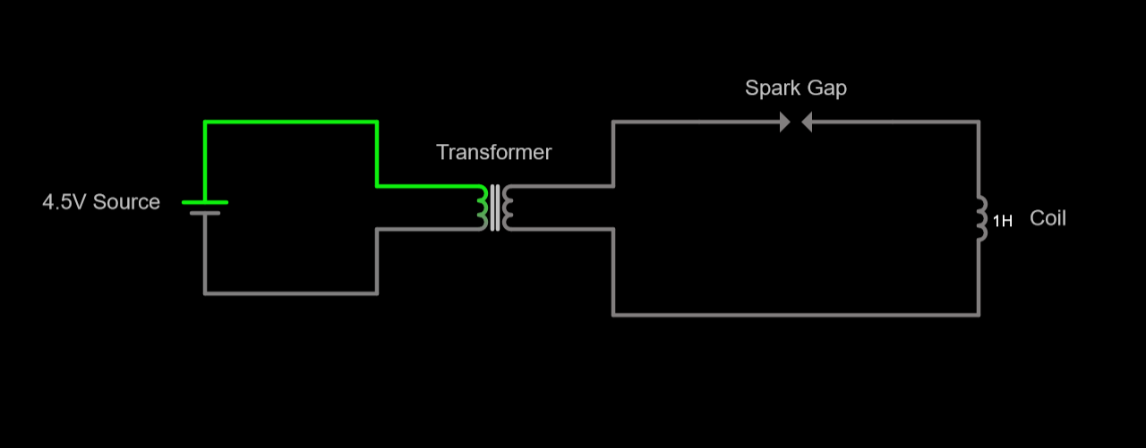
Design
It's been a long time since I worked on this project (I am currently writing this in 2024) so I don't have many of the initial designs. However, I do remember the key components and how I worked with them:
- A 4.5V power source (consisting of 3 AA batteries and a battery pack)
- A (very sketchy) transformer that scaled up the 4.5V to a nominal 30kV (more on this later)
- A custom-made spark gap to create pulses of high current
- A coil of magnet wire wrapped around an iron core to produce magnetic fields
The principle that this device operated on was that the ionization of air creates temporary high-current pulses that can create short-lived but powerful magnetic fields that can disrupt low-power electronics. The circuitry in the device is dedicated to making these current pulses, and the magnetic coil is what turns these current pulses into magnetic field pulses. The way the circuit works is that a small voltage is applied to the input of the transformer, which creates a high-voltage-but-low-current output. To transform the high voltage into a momentary high current, a spark gap is employed. The idea is that if enough voltage builds up on one side of the spark gap, it can cause the air between the two electrodes to temporarily ionize. Air has a very high electrical resistance (about 30kΩ/cm if I remember correctly) but when ionized, has a very low electrical resistance. This makes the spark gap behave like an electrical component that can switch between a very high and very low resistance, which allows for it to switch between ~0 mA and a very high current. When that very high current is fed into a coil of wire, the resulting magnetic fields would (hopefully) be strong enough to observe disruption in other nearby electronics.
The Power Source
The power source for the EMP device was chosen based on the requirements of the transformer (discussed below). I chose a transformer that claimed to scale input voltages between 3V and 6V up to about 30kV, so I chose a power source that supplied a voltage right at the median. Conveniently, since AA batteries are rated to supply 1.5V each, I needed a power source that included 3 of them in series. Originally I considered making my own using tin foil and tape, but this project was already going to be very sketchy. I decided to look on Amazon to see if electronics companies made those little plastic battery cases for 3 batteries specifically, and it turns out they do! I bought one of those and used that as the main power source for the device.
The Transformer
The transformer plays a really important role in the circuit, as it generates high voltages that can be transformed into magnetic pulses that affect other electronics. I wasn't sure exactly how strong of a transformer I was going to need since I did not have the knowledge to translate high voltages into the amplitude of magnetic pulses, nor the understanding of how strong the magnetic pulses needed to be to fry electronics. After a bit of searching online I found a cheap transformer that claimed to scale voltages from 3V-6V up to 30kV, which sounded strong enough to me at the time. I admit this isn't really great engineering design, but I also barely understood circuit design to begin with, so the bar isn't very high for this project.
The Spark Gap
The spark gap is where I had to get the most creative for this project. As it turns out, you can't search for "spark gaps" online and just purchase one. So, I decided that I needed to figure out how to build one on my own. I figured it wouldn't be that challenging since the operating principle is so simple. You basically just need two conductive electrodes separated by some fixed distance, and by running a high voltage through them, ionization of air turns high voltages into high currents.
The way I approached this was by using two small metal screws as my electrodes. They were dirt cheap, simple, and I already had some on hand. From there, I needed an easy way to keep them separated from each other by a fixed distance without them moving much. I decided to take a crack at designing a simple 3D-printed bracket that they could be inserted into. It took me a few iterations, but I eventually landed on a design that was both sturdy enough to hold the screws in place while also providing the right distance. There was only a very specific range you could screw a screw into the bracket and have it be sturdy, so I needed the length of the bracket to match the window of distance where the spark gap would operate correctly. Given that the transformer I picked produced a real voltage much lower than the nominal voltage (more on this later), this took some trial and error to figure out what the length should be.
The Coil
When I was researching the topic of EMP devices, I found a couple of good tips on the internet about how to build the coils for the best performance. Firstly, it was recommended to me to use "magnet wire" as opposed to regular wire. The only difference between them is that magnet wire is bare copper wire with a special enamel coating, that (for reasons I don't fully understand) makes it more suitable for building magnetic coils. I assume that it is to prevent adjacent copper wires from touching each other and short circuiting the coil, but the part I don't understand is why this specific coating is better.
Anyways, the second key recommendation was to use an iron core and NOT a steel core. The reason is because iron works better for electromagnetic applications rather than steel because while they both magnetize nicely, steel has a habit of retaining magnetization when the device is powered off. For an electromagnet to work, it needs to both magnetize and demagnetize effectively. I decided to use a small pipe segment similar to what you could find at a home hardware store. It's cylindrical, about 15cm long, has a diameter of roughly 3.5cm, and was hollow. Surprisingly, it is pretty difficult to just go out and buy a pipe made of just iron, as most of them these days are some kind of steel. I did my best to find one that was just "iron" and went with that.
Assembling the coil was pretty easy. I just took the magnet wire and tightly wrapped it around the iron core. I then taped the ends so that the wire wouldn't fall off, mostly because I didn't have a better solution. I was able to squeeze in somewhere between 60 and 100 windings around the core, which I thought was decent.
Results
After some tuning of the width of the spark gap, I was able to get it to consistently disrupt the functionality of low-power electronic calculators. When placed near these calculators, the voltage induced in the calculators' circuitry caused "ghost keystrokes" where numbers were being entered into the calculator's memory without the buttons being physically pressed. It was also able to disrupt the LCD screen and make it display invalid characters when the coil was placed on top of it.
Overall, the project was a success! I even got a 100% for the project in my physics class too. My physics teacher was very impressed with the result.
One thing I didn't like about the project is that I never got to make a proper casing for the EMP device. I had designed the "guts" of the device, and they worked, but there was no nice container for it all. I was trying to design a handheld device that contains all the parts but couldn't finalize a design ahead of the project's deadline, so I just had to demonstrate a video of the working prototype working at my house.
I also recognize that this was a somewhat dangerous project with the open spark gap and all that. I wasn't too concerned with it at the time because even though the device looks and sounds scary when in operation, given the low power source I figured it wouldn't be fatal. If I were to ever do a V2 of this project, I would for sure enclose that spark gap so that it doesn't pose any sort of risk.
Speaking of a possible V2, there are a number of improvements I would make to the circuit. Firstly, I would add a resistor between the input to the transformer and the negative terminal of the power source. When I built this circuit I'm lucky that having (essentially) a zero-resistance connection from the positive end to the negative end of the power source didn't short it/cause any problems. I would absolutely introduce a resistive element next time to prevent this from being a serious electrical issue. Additionally I would also choose a better transformer to scale up the voltage. As I hinted at above, the transformer I chose was extremely sketchy. I bought it off of Amazon, and it came from some random Chinese electronics company. It advertised scaling input voltages of 3V-6V all the way up to 30kV, but in practice I think it only scaled up to about 12kV. I wasn't able to measure the voltage directly but I was able to deduce it by tuning the spark gap. As I understand it, air has an ionization constant of about 30kV/cm, which means that if you want to create arcs of electricity that are 1 centimeter long, you need 30kV to do so. I found that I couldn't get arcs of electricity to form until I shortened the spark gap to about 0.4cm / 4mm, which based on this constant implies that there is a voltage of 12kV being applied to the spark gap. Thankfully this wasn't an issue, because the voltage was still high enough to produce strong momentary magnetic pulses that were just enough to affect the test electronics.